
| Run the Applet | Examples | Source Code |
|---|
The Vortex Panel Method Applet is a computational tool for students studying the aerodynamics of airfoil sections. The vortex-panel method is a method for computing ideal flows - flows in which the effects of compressibility and viscosity are negligible. Ideal flow is often the first type of fluid motion that student engineers and scientists study, because it is the simplest. Large parts of the flows past ships, submarines, cars and light aircraft are closely ideal. The following description assumes the reader has had some theoretical introduction to this subject (e.g. as given by J. J. Bertin and M. L. Smith, Aerodynamics for Engineers, Second Edition, Prentice Hall, 1989, or A. M. Kuethe and C.-Y. Chow Foundations of Aerodynamics, Fourth Edition, Wiley, 1985).
Ideal fluid flows are solutions to Laplace's equation. This differential equation is linear, which means that adding together (superposing) any number of ideal flows produces a new ideal flow. One approach to finding the solution to complex flow problems - termed superposition - is therefore to begin with very simple ideal flows, that are easily understood and described, and then to add them together to produce the complex flow patterns desired. This process is modeled in its most simplest form in the Ideal Flow Machine applet in which elementary flows such as sources, vortices and uniform flows can be combined and the resulting flows visualized. The Vortex Panel Method applet goes one step further, and applies the principle of superposition to a practical application - the analysis of airfoil flows.


As can be seen in figure 3, each panel produces an elongated rotating flow - the panel is actually a concentrated sheet of vorticity. In general the strength of a panel can vary along its length in an arbitrary way. In this realization of the vortex panel method we assume that the strength of each panel varies linearly over the panel and the strength is continuous across the panel joints, except at the trailing edge (see figure 1). This means that, after drawing the N panels around the airfoil, we have N+1 strengths to specify (one at each panel joint and two at the trailing edge, the variations being then linear across each panel). The problem is to choose these strengths so that the flow past the panels is a realistic representation of the flow over the airfoil. To do this we invoke the so-called 'non-penetration' condition - the condition that the flow cannot pass through the surface of the airfoil or, equivalently, that the component of velocity perpendicular to the airfoil surface is zero. We apply this condition approximately by writing equations for the velocity generated by all the panels, plus the free stream, at the central point of each panel (called the control points, see figure 1). We then set the component of this velocity perpendicular to the panel equal to zero. Since we have N control points this gives us N equations for the N+1 strengths. The final equation is obtained using the Kutta condition. The Kutta condition encapsulates the observation that the flow can't go around the trailing edge, but must leave the airfoil there. This is a consequence of viscous effects, which are otherwise is absent from this calculation. For the Kutta condition to be satisfied the the strengths of the vortex panels must be equal and opposite where they meet at the trailing-edge joint. All that now remains is the solution of N+1 simultaneous equations for the N+1 unknown strengths (via a matrix inversion), and then the evaluation of the flow properties of interest. This is precisely what is done by the Vortex Panel Method Applet.

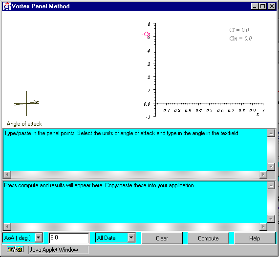
The top half of the window contains a graphics panel where the airfoil shape and aerodynamic results are plotted. The bottom half contains two text areas and a row of controls. The upper text area is the input table - where you provide the coordinates that specify the shape of the airfoil. The lower text area is the output table where the results of the calculation are listed. The controls include a 'Help' button, that brings up a window with some abbreviated instructions, a 'Compute' button that starts the calculation, a 'Clear' button that clears the input and output tables, a text area where you specify the angle of attack, a selector where you can specify whether the angle of attack is in degrees or radians, or refers to a single value or range, and a selector (default 'All Data') which enables you to specify the format of the results appearing in the output table. To perform a calculation, proceed as follows -
William Devenport
| Run the Applet | Examples |
|---|